Anleitungen / instructions A ... L
- Alphakanal-alphachannel
- Bedingungen-conditions
- Bezierkurven-Beziercurves
- Diaeffekte-slide effects
- Drehbank-lathe
- Felder-arrays
- Höhenfelder-heightfields
- Isosurface-isosurface
- Kamera-camera
- LParser-LParser
- Start - Theorie/theory
- Homepage
Alphakanal / alphachannel
Erstellt man eine neue Grafik, so besteht das Bild zunächst aus einer Hintergrundebene, vorstellbar als Leinwand unter einem Gemälde. Sollen nur einzelne Bildbereiche verändert werden, so kann man eine neue Ebene öffnen, dort arbeiten, Bildelemente ändern ohne die erste(n) Ebene(n) zu beinflussen.
If you create a new graphic, the image initially consists of a background layer, imaginable as a canvas under a painting. If you only want to change individual areas of the image, you can open a new layer, work there and change image elements without affecting the first layer(s).
Sollen nun Teile einer Ebene nicht sichtbar sein., so wird ein Graustufenbild, eine sog. Maske auf die Ebene gelegt, deren Grauwert bestimmt, wieviel von der maskierten Ebene sichtbar bleibt.
If parts of a layer are not to be visible, a grayscale image, a so-called mask, is placed on the layer whose gray value determines how much of the masked layer remains visible.

- Um eine Maske zu erstellen, kopiert man den zu projektierenden Bildbereich mit Hilfe des "Zauberstabwerkzeugs" auf ein Bild mit transparenten Hintergrund.
- Man wählt nun die Option "neue Maske erstellen" und speichert diese Maske in den Alphakanal des Bildes, sichert dann das ganze Bild in einem für PoVRay geeigneten Bildformat. Der Alpha-Kanal ist ein Graustufenkanal, der für die Maskensicherung benutzt werden kann. Ein Kanal enthält alle Pixelinformationen für eine bestimmte Farbe: Ein Kanal für Grausufenbilder, drei für Rot-Grün-Blau-Bilder.
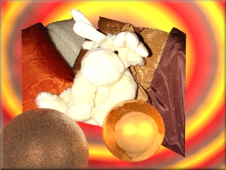
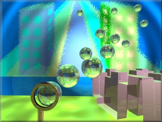
- Wird dieses Bild nun in PoVRay auf z.B. eine Kugel projiziert, dann ist der Bildhintergrund transparent, die Kugel wird nur dann sichtbar, wenn man ihr reflektierende oder lichtbrechende Eigenschaften zuteilt.
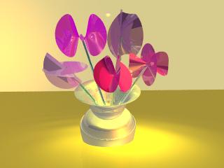
- Die Deckfähigkeit der Ebene kann vor der Maskenerstellung verändert werden, man erhält dann eine graue Maske, die eine schwach durchscheinende Bildvorlage erzeugt: siehe rechte Spalte im Demobild oben!
The opacity of the layer can be changed before the mask is created, you will then get a gray mask that creates a slightly translucent image template: see right column in the demo image above!
To create a mask, copy the image area to be projected onto an image with a transparent background using the magic wand tool.
Now select the option Create new mask and save this mask in the alpha channel of the image, then save the entire image in an image format suitable for PoVRay. The alpha channel is a grayscale channel that can be used for mask saving. One channel contains all the pixel information for a specific color: one channel for grayscale images, three for red-green-blue images.
If this image is now projected onto a sphere in PoVRay, for example, the background of the image is transparent and the sphere only becomes visible if it is assigned reflective or refractive properties.
Bei Mausklick auf das ff. Bild, kann das zugehörige Skript eingesehen werden.By clicking on the ff. image, the corresponding script can be viewed.
|
Bedingtes Programmieren: Fallunterscheidungen mit SWITCH, CASE, RANGE
Conditional programming: Case distinctions with SWITCH, CASE, RANGE
PoVRay bietet mehrere Möglichkeiten zum bedingten Bildumwandeln. Zwei davon sollen hier vorgestellt werden. Nicht nur bei der Erstellung von Animationen, sondern auch beim Erzielen anderer Effekte ist dies nützlich.
PoVRay offers several options for conditional image conversion. Two of these are presented here. This is useful not only for creating animations, but also for achieving other effects.
Für die Syntax des Schalters SWITCH gilt: The following applies to the syntax of the SWITCH button:
#switch (Variable)
     #case (Variablenwert_1)
        ..........
     #break  //beendet Fall 1

     #case (Variablenwert_2)
        ..........
     #break  //beendet Fall 2
#end
Falls die Variable den Wert "Variablenwert_1" hat, wird der erste Teil des Skripts umgewandelt, bei "Variablenwert_2" der zweite Teil. Auch die Verwendung von #ELSE ist erlaubt..
If the variable has the value "Variablenwert_1", the first part of the script is converted, for "Variablenwert_2" the second part. The use of #ELSE is also permitted.
Beispiel / example:
#switch (Farbwechsel)
   #case (1)
         pigment {color DarkOrchid}
   #break
   #case (0)
         pigment {color MediumAquamarine}
   #break
#end
Dabei ist "Farbwechsel" eine Variable, die innerhalb einer Zählschleife ihren Wert dauernd von 1 zu 0 und 0 zu 1 wechselt. Im Skript "schalt_2.pov" wird dieses Beispiel verwendet.
Here, "Farbwechsel" is a variable that constantly changes its value from 1 to 0 and 0 to 1 within a counting loop. This example is used in the "schalt_2.pov" script.
Analog zur Verwendung von CASE kann auch RANGE verwendet werden. Mit '#range(a,b)' wird dann derjenige Skriptabschnitt in ein Bild umgewandelt, für den die in '#switch (variable)' gewählte Variable im Bereich von a bis b liegt. Die Syntax ist dieselbe wie bei CASE, auch hier darf ELSE verwendet werden.
RANGE can also be used in the same way as CASE. With #range(a,b), the script section, for which the variable selected in #switch (variable) lies in the range from a to b, is then converted into an image. The syntax is the same as for CASE, ELSE may also be used here.
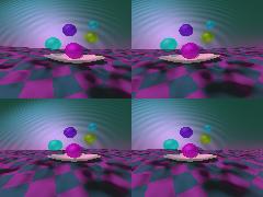
Mausklick auf die ff. Beispielbilder zeigt das zugehörige Skript / Click on the following example images shows the corresponding script:
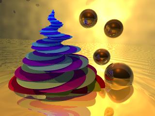
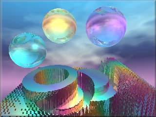
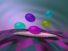
Im ersten Bild wurde SWITCH überhaupt nicht eingesetzt, es wurde nur die Variable "Farbwechsel" so definiert, daß sie innerhalb der Zählschleife abwechselnd die Werte 0 und 1 annimmt. Dies wurde dann in der Pigment-Definition als Grünanteil eingesetzt. So entstand die abwechselnde Einfärbung der Scheiben.
In the first image, SWITCH was not used at all, only the variable Farbwechsel was defined in such a way, that it alternately assumes the values 0 and 1 within the counting loop. This was then used in the pigment definition as the green component. This is how the alternating coloring of the panes was created.
|
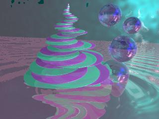
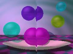
Im zweiten Bild wurde dann CASE in Abhängigkeit von FARBWECHSEL eingesetzt (siehe obiges Beispiel), der Spiralkörper hat 2 Farben, die abwechseln auftauchen.
In the second image, CASE was then used as a function of FARBWECHSEL (see example above), the spiral body has 2 colors, which appear alternately.
|
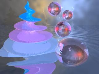
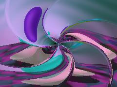
Das dritte Bild ist unter Verwendung von RANGE(zaehler) entstanden. Auf diese Weise wurden drei Farbbereiche festgelegt.
The third image was created using RANGE(zaehler). In this way, three color ranges were defined.
|
Bezierkurven / Beziercurves
Bezier-Verbindungslinie beim Drehbankobjekt können seit Version 3.1 benutzt werden, ebenso wie lineare, quadratische und kubische Verbindungslinien.
Für ein Segment werden 4 Punkte benötigt:
Bezier connection lines can be used for lathe objects since version 3.1, as well as linear, square and cubic connection lines. 4 points are required for a segment:
Die Punkte 1 und 4 bestimmen dabei Anfang und Ende eines Segments. Die Verbindungslinie zw. Punkt 1 und Punkt 2 bestimmt die Steigung der Kurve in Punkt 1 (Tangente), die Verbindungslinie zw. Punkt 4 und Punkt 4 bestimmt die Steigung in Punkt 4 (Tangente), was in obiger Abbildung verdeutlicht wurde. Zeichnet man sich die Linien auf ein Koordinatensystem, so kann man auf einfache Art die Form eines Drehbankobjekts planen.
Points 1 and 4 determine the start and end of a segment. The connecting line between point 1 and point 2 determines the gradient of the curve at point 1 (tangent), the connecting line between point 4 and point 4 determines the gradient at point 4 (tangent), as illustrated in the figure above. If you draw the lines on a coordinate system, you can easily plan the shape of a lathe object.

|
|

|
Diaeffekte mit image_map / slide effects using image_map
Mit den Schlüsselwörtern image_map, filter und transmit können auch Dia- und BlueScreen-Effekte erzielt werden.
The keywords image_map, filter and transmit can also be used to create slide and blue screen effects.
Farbdefinitionen werden bei PovRay vektoriell erstellt / color definitions are created vectorially in PovRay.:
color rgb <1,0,0>
Die drei ersten Komponenten des Vektors sind der Rot-, Grün- und Blauanteil der gewünschten Farbe. Im obigen Beispiel beträgt der Rotanteil 100%, Grün und Blau sind nicht vorhanden.
Als vierte Vektorkomponente kann das Schlüsselwort 'filter' hinzukommen:
The first three components of the vector are the red, green and blue components of the desired color. In the example above, the red component is 100%, green and blue are not present.
The keyword 'filter' can be added as the fourth vector component:
color rgbf <1,0,0,0.5>
Da der Filtereffekt durch Absorption unerwünschter Wellenlängen des Lichts (es wird so gefiltert, als würde es durch eine rot gefärbte Folie scheinen) entsteht, spricht man auch von subtraktiver Transparenz. Die so gefärbten Objekte werfen also einen farbigen Schatten. Mit obigem Beispiel können u.a. farbige Verglasungen realisiert werden. 'filter' spezifisiert den Betrag des noch hindurchgehenden gefilterten Lichts.
Die fünfte Vektorkomponente ist 'transmit':
As the filter effect is created by absorbing unwanted wavelengths of light (it is filtered as if it were shining through a red-colored film), this is also referred to as subtractive transparency. Objects colored in this way cast a colored shadow. The above example can be used to create colored glazing, for example. 'filter' specifies the am
ount of filtered light still passing through. The fifth vector component is transmit:
color rgbt <1,0,0,0.7>
Trifft weißes Licht (alle Wellenlängen sind vorhanden) auf ein so gefärbtes Objekt, so erfolgt eine Intensitatsschwächung, alle Wellenlangen werden zu einem bestimmten Betrag durchgelassen, die Wellenlänge für rotes Licht passiert ungehindert. Man spricht hier auch von additiver Transparenz.
If white light (all wavelengths are present) hits an object colored in this way, the intensity is weakened, all wavelengths are transmitted to a certain extent, the wavelength for red light passes unhindered. This is also referred to as additive transparency.
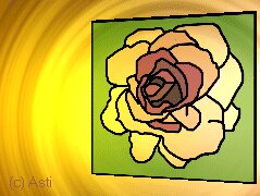
Im ersten Beispiel wurde mit 'transmit' die Tiffany-Rose transparent gemacht, sodass der Hintergrund durchscheint. Im nächsten Bild wurden mit 'filter' farbige Lichtstreifen in der Atmosphäre erzeugt.
In the first example, transmit was used to make the Tiffany rose transparent, so that the background shines through. In the next image, filter was used to create colored stripes of light in the atmosphere.
 |
 |
Drehbankobjekte / lathe
Durch Angabe der x- und y-Koordinaten werden Punkte in der x-y-Ebene festgelegt, sodaß dann bei Rotation um die y-Achse ein Drehobjekt entsteht. Die z-Komponente des zugehörigen Vektors wird als Null vorausgesetzt. Im Unterschied zum SOR (surface of revolution) unterscheidet das Drehbank-Objekt zwischen linearer, quadratischer und kubischer Verbindungslinie zwischen den angegebenen Punkten.
Während bei SOR dieselbe y-Koordinate nicht zweimal verwendet werden darf, ist dies beim Drehbank-Objekt erlaubt, die Bildumwandlungszeit ist dafür länger als bei SOR.
By specifying the x and y coordinates, points are defined in the x-y plane so that a rotation object is created when rotating around the y axis. The z-component of the associated vector is assumed to be zero. In contrast to SOR (surface of revolution), the lathe object distinguishes between linear, quadratic and cubic connecting lines between the specified points.
While the same y-coordinate may not be used twice with SOR, this is permitted with the lathe object, but the image conversion time is longer than with SOR.
Bei Verwendung der Punkte / using the following points
#declare Red_Point = <1.00, 0.00, 0>
#declare Orange_Point = <1.75, 1.00, 0>
#declare Yellow_Point = <2.50, 2.00, 0>
#declare Green_Point = <2.00, 3.00, 0>
#declare Blue_Point = <1.50, 4.00, 0>
entsteht bei Verwendung linearer Verbindungslinien die ff. Form / the following form is created when linear connecting lines are used. :
Ändert man nun die Punkte zu / changing the points
#declare Red_Point = <1.00, 0.00, 0>
#declare Orange_Point = <2.00, 1.00, 0>
#declare Yellow_Point = <3.50, 2.00, 0>
#declare Green_Point = <2.00, 3.00, 0>
#declare Blue_Point = <1.50, 4.00, 0>
und verwendet quadratische Verbindungslinien, so erhält man / and using square connecting lines, you get
Zwar sind die Punkte durch quadratischen Linienverlauf verbunden, der rote Punkt ist jedoch im Drehkörper nicht mehr enthalten: da man zur Definition einer Geraden nur zwei Bestimmungspunkte braucht, zur Definition einer quadratischen Funktion jedoch drei, verwendet POVRAY den ersten Punkt zur Bestimmung der Funktionsgleichung! Analog werden für kubische Funktionen vier Punkte benötigt.
Although the points are connected by a quadratic line, the red point is no longer contained in the solid: since you only need two points to define a straight line, but three to define a quadratic function, POVRAY uses the first point to determine the equation of the function! Similarly, four points are required for cubic functions.
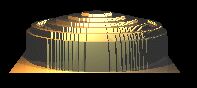
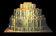
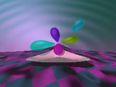
Mit dem Drehbank-Objekt kann man auf einfache Weise Tiegelchen und Töpfchen in allen Variationen produzieren. Ein Beispiel zur lathe-Syntax findet Ihr im Skript zu nächsten Abbildung (Mausklick auf das Bild zeigt das Skript)
With the lathe object you can easily produce jars and pots in all variations. An example of the lathe syntax can be found in the script for the next illustration (click on the image to open the script)
 |

FELDER - ARRAYS
Seit Version 3.1 gibt es nun ein- oder mehrdimensionale Felder (arrays). Ein eindimensionales Feld kann man sich als eine Liste vorstellen, die Listenelemente sind dabei über Indizes ansprechbar und müssen vom gleichen Typ sein. Sie müssen definiert (initialisiert) werden.
Since version 3.1, there are now one- or multi-dimensional arrays. A one-dimensional array can be imagined as a list; the list elements can be addressed via indices and must be of the same type. They must be defined (initialized).
Beispiel für ein eindimensionales Feld aus drei Elementen / Example of a one-dimensional array consisting of three elements:
#declare Schöne_Texturen=array[3];
#declare Schöne_Texturen[1]=pigment {Jade}
#declare Schöne_Texturen[2]=pigment {Water}
Eine Fehlermeldung ergäbe / you'd get an error message
#declare Schöne_Texturen[1]=normal {dents 0.5}
da hier nicht der gleiche Datentyp vorliegt. Eine Fehlermeldung würde auch die ff. Zeile ergeben:
as the data type is not the same here. An error message would also result, when usingthe following line :
#declare Oberfläche=Schöne_Texturen[3]
da das 3. Listenelement oben nicht definiert (initialisiert) wurde / as the 3rd list element above was not defined (initialized)..
Da es mühsam ist, jedes Listenelement einzeln zu initialisieren, gibt es eine abkürzende Syntax:
As it is tedious to initialize each list element individually, there is a shortcut syntax:
#include "textures.inc"
#declare Schöne_Texturen = array[3] {Jade, Water, Red_Marble}
Nun darf auch '#declare Oberfläche=Schöne_Texturen[3]' verwendet werden, da nun das 3. Listenelement initialisiert wurde.
Now #declare surface=beautiful_textures[3] can also be used, as the 3rd list element has now been initialized.
Beispiel für ein mehrdimensionales Feld aus 20 Elementen / Example of a multidimensional field consisting of 20 elements:
#declare Ziffernblock =
      array[2][10]
      {{01,02,03,04,05,06,07,08,09,10},{11,12,13,14,15,16,17,18,19,20}}
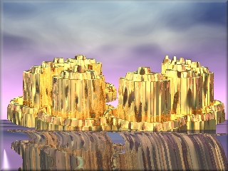
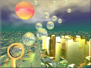
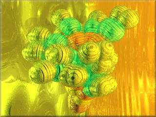
Für "Rubics Cube" links neben der Überschrift wurde ein mehrdimensionales Feld zur Definition der Texturen für die einzelnen 9 Würfelspalten benutzt. Mausklick auf´s Bild zeigt das zugehörige PovSkript. Im mittleren Bild wurde nur ein 1x3 Feld benötigt, da die Definition der Kugelmittelpunkte von der inneren Zählschleife in die mittlere verschoben wurde (vgl. Skript).
For "Rubics Cube" to the left of the heading, a multidimensional array was used to define the textures for the individual 9 cube columns. Click on the image to see the corresponding PovScript. In the middle image, only a 1x3 array was needed because the definition of the sphere centers was moved from the inner counting loop to the middle one (see script).
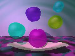
Im fogenden Bild wurde ein eindimensionales Feld für die Definition der Kugelfarben verwendet, mit Hilfe von 'switch' und der Funktion 'vlength' wurden die Farben verteilt.
In the following image, a one-dimensional array was used to define the sphere colors, with the help of 'switch' and the function 'vlength' the colors were distributed.
 |
... und immer noch gilt / and don't forget:
Fahnenstocks goldene Regel für Fehlschläge / Fahnenstock's golden rule for failures:
Wenn du auf Anhieb keinen Erfolg hast, vernichte alle Hinweise darauf, dass du es jemals versucht hast.
If you don't succeed right away, destroy all evidence that you ever tried.
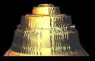
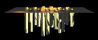
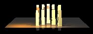
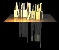
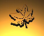
Höhenfelder / Height_fields
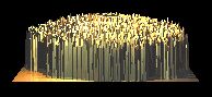
Höhenfelder (height_fields) sind Würfel der Kantenlänge 1 LE, deren obere Fläche gebirgig ist. Der Würfel liegt in der x-z-Ebene, seine vordere linke untere Ecke befindet sich im Koordinatenursprung. Die Höhe jedes Punktes hängt von der Palettenfarbe der verwendeten Grafikdatei ab. Dabei spielt die Auflösung des verwendeten Bildes für die Skalierung des Höhenfeldes keine Rolle. Bei höherer Auflösung wird das Höhenfeld weicher gezeichnet. Die zughörige POVRAY-Syntax ist:
Heigh_fields are cubes with an edge length of 1 LE whose upper surface is mountainous. The cube lies in the x-z plane, its front bottom left corner is in the coordinate origin. The height of each point depends on the palette color of the graphics file used. The resolution of the image used does not play a role in the scaling of the height field. At higher resolutions, the height field is drawn softer. The corresponding POVRAY syntax is:
height_field { gif "bildname.gif" }
TGA und PNG-Bilder können ebenfalls verwendet werden / TGA and PNG images can also be used.
Farben mit kleinem Palettenindex liegen tiefer im Höhenfeld. Ein Bild der Farbe 0 ergibt eine Ebene, ein Bild der Farbe 255 ergibt einen Würfel der Kantenlänge 1 LE. Die Farbe des Palettenindex´spielt für die Höhe des zugehörigen Punktes keine Rolle, nur die Nummer der Farbe in der Palette wird ausgewertet!
Colors with a small palette index are lower in the height field. An image of color 0 results in a plane, an image of color 255 results in a cube with an edge length of 1 LE. The color of the palette index is irrelevant for the height of the corresponding point, only the number of the color in the palette is evaluated!
Der Parameter ´water_level´ gefolgt von einer Zahl zwischen 0 und 1 kann nach dem Bildnamen hinzugefügt werden, sodaß unterhalb dieses Wertes das Höhenfeld nicht angezeigt wird. (Beispiel: ´water_level 0.5´ heißt, daß nur die obere Hälfte des Höhenfeldes grafisch umgesetzt wird. Auf diese Weise können unerwünschte tiefere Werte weggeschnitten werden. Das Schlüsselwort ´smooth´ glättet das Höhenfeld.
The parameter water_level followed by a number between 0 and 1 can be added after the image name so that the height_field is not displayed below this value. (Example: water_level 0.5 means that only the upper half of the height field is displayed graphically. In this way, unwanted lower values can be cut away. The keyword smooth smoothes the height_field.
Höhenfelder können für CSG (Constructive Solid Geometry) verwendet werden, man kann sie skalieren, transformieren, rotieren.
Height_fields can be used for CSG (Constructive Solid Geometry), they can be scaled, transformed and rotated.
Die folgende Tabelle zeigt Höhenfelder mit den zugehörigen Bildvorlagen / The following table shows height fields with the corresponding image templates.
| 
| 
| 
|

| 
| 
| 
|
| 
| 
| 
|
| 
| 
| 
|
| 
|
 |
 |
 |
 |
 |
|
Isosurface - algebraische Flächen / algebraic surfaces
Bekannt sind Isolinien: / Isolines are well-known:
Isobaren / Isobars: Punkte gleichen Luftdrucks werden miteinander verbunden. / Points of equal air pressure are connected to each other.
Isothermen / Isotherms: Punkte gleicher Temperatur werden miteinander verbunden / Points of the same temperature are connected to each other.
Isohypsen / Isohypses: Punkte gleicher Höhe über dem Meeresspiegel werden miteinander verbunden (Höhenlinien) / Points at the same height above sea level are connected (contour lines).
Ebenso kann man bei 3-dimensionalen Flächen Raumpunkte mit gleichen Merkmalen miteinander verbinden und erhält dann Isoflächen.
You can also connect spatial points with the same characteristics for 3-dimensional surfaces and then obtain isosurfaces.
Mit dem Schlüsselwort 'isosurface' kann man in PoVRay eigene Funktionen definieren oder voreingestellte verwenden.
Die Gleichung x2 + y2 - 4 = 0 stellt bekanntlich einen Kreis um den Koordinatenursprung mit Radius r = 2 dar.
Analog kann 3-dimensional die Gleichung für eine Kugeloberfläche angegeben werden: x2 + y2 + z2 - 4 = 0.
With the keyword isosurface you can define your own functions in PoVRay or use preset ones. The equation x2 + y2 - 4 = 0 is known to represent a circle around the coordinate origin with radius r = 2.
Similarly, the equation for a spherical surface can be specified in 3 dimensions: x2 + y2 + z2 - 4 = 0.
Betrachtet man nun die Relation R = x2 + y2 + z2 - 4 und sucht sich all die Punkte heraus, für die R denselben Wert hat, so erhält man die Punkte, die auf der Oberfläche der Kugel liegen: ISOSURFACE.
Der Wert von R wird in der PoVRay-Syntax durch 'threshold' festgelegt.
Ein "Container" ist nötig, um die 3D-Fläche zu begrenzen.
If we now consider the relation R = x2 + y2 + z2 - 4 and look for all the points for which R has the same value, we obtain the points that lie on the surface of the sphere: ISOSURFACE.
The value of R is defined in the PoVRay syntax by threshold.
A container is required to limit the 3D surface.
Beispiel 1 / 1st example
#declare IsoFinish = finish {ambient 0 diffuse 1
                             specular 1 roughness 0.02
                             brilliance 2}

isosurface {
  function { pow(x,3)+pow(y,2)-pow(z,2) }
        threshold 0
        max_gradient 4
        contained_by {box {-1,1} } open
                                    //die Ränder des Containers fallen weg!
                texture {pigment {color Coral} finish {IsoFinish}}
        scale 1/vlength(1)
        scale 10
        rotate <130, -30, 90>
           }//end isosurface
Obige Zeilen liefern das folgende Bild / The lines above provide the following picture:
|
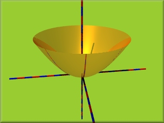
Beispiel 2 / 2nd example
x2+ y2 = z hat als Lösungsmenge ein Drehparaboloid: Wählt man P(x/y) frei in der Ebene und trägt darüber als Höhe x2 + y2 ab, dann stellt dies die Lösungsmenge dar.
x2+ y2 = z has a paraboloid of revolution as the solution set: If you choose P(x/y) freely in the plane and enter x2 + y2 as the height, then this represents the solution set.
isosurface {
  function {pow(x,2)+pow(y,2)-z}
        threshold 0
        max_gradient 4
        contained_by {box {-1,1} } open
                texture {
                pigment {color Coral}
                finish {F_MetalC}
        }
        scale 1/vlength(1)
        scale 10
        rotate <180, 90, -90>
        translate < 0, 0, 0>
 }
|
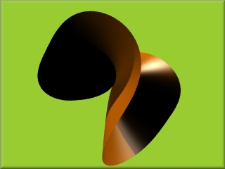
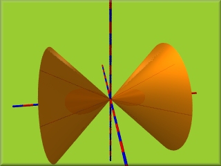
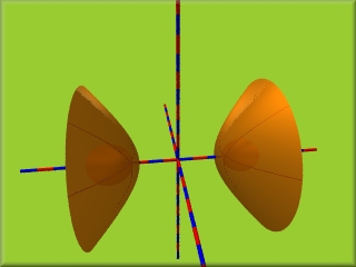
Beispiel 3 / 3rd example
x2 - y2 = z2 hat einen Doppelkegel als Lösungsmenge.
x2 - y2 = z2 has a double cone as a solution set.
isosurface {
  function {pow(x,2)-pow(y,2)-pow(z,2)}
        threshold 0
        max_gradient 4
        contained_by {box {-1,1} } open
                texture {
                pigment {color Coral}
                finish {F_MetalA}
        }
        scale 1/vlength(1)
        scale 10} //end isosurface
|
Beispiel 4
Verändert man die Gleichung x2 - y2 = z2 nur leicht und ersetzt sie durch
x2 - y2 - z2 = 0,2 (Änderung von 'threshold 0' zu 'threshold 0.2')
dann fällt die Singularität (Spitze) weg und man erhält zwei abgerundete Schalen.
If you change the equation x2 - y2 = z2 only slightly and replace it with x2 - y2 - z2 = 0.2 (change from 'threshold 0' to 'threshold 0.2') then the singularity (peak) disappears and you get two rounded shells.
isosurface {
  function {pow(x,2)-pow(y,2)-pow(z,2)}
        threshold 0.2
        max_gradient 4
        contained_by {box {-1,1} } open
                texture {
                pigment {color Coral}
                finish {F_MetalA}
        }
        scale 1/vlength(1)
        scale 10

 }
|
Weitere Informationen zu Algebraischen Flächen, Singularitäten, ... erhältst Du auf meiner Seite Mathematische Streiflichter, wenn du dort im Hauptmenü den Punkt 'Isoflächen' wählst.
Further information on algebraic surfaces, singularities, ... can be found on my website Mathematische Streiflichter, if you select the item 'Isosurfaces' in the main menu.
Einen Überblick über 3D-Flächen mit zugehöriger Gleichung gibt Tore Nordstrand.
An overview of 3D surfaces with the corresponding equation is provided by Tore Nordstrand.
Einen weiteren Überblick über mathematische Flächen findet ihr hier.
You can find another overview of mathematical surfaces here.
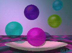
Die Kameraeinstellung in PoVRay / The camera setting in PoVRay
Bei den folgenden zwei Bildern wurde die perspektivische Projektion verwendet (=Normaleinstellung der PovRay-Kamera). Sie sollen die Verwendung von "focal_point" bei der Kameraeinstellung sowie die Verwendung von color rgbt und color rgbf (vgl. Skript, per Mausklick auf das Bild einsehbar) verdeutlichen.In the following two images, the perspective projection was used (= normal setting of the PovRay camera). They are intended to illustrate the use of focal_point in the camera setting and the use of colour rgbt and colour rgbf (see script, can be viewed by clicking on the image).
Mit / With
focal_point < x,y,z>
aperture 0.6
blur_samples 12
wird der Brennpunkt für die "Aufnahme" des Bildes eingestellt und der Bildausschnitt festgelegt (größere Zahl ergibt kleineren scharfen Ausschnitt), die 3. Zeile bestimmt die Anzahl der Lichtstrahlen, die auf einen Bildpunkt treffen.
the focal point for capturing the image is set and the image section is defined (larger number results in smaller sharp section), the 3rd line determines the number of light rays that hit a pixel.
| 
|
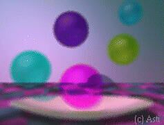
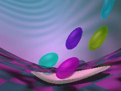
Durch Verwendung des Schlüsselwortes 'normal' werden die Lichtstrahlen zwischen Kamera und Objekt durch das "Normalenmuster" gestört. Dabei ergeben sich teils interessante Effekte. Anhand des Skriptes (Mausklick aufs Bild) könnt Ihr das beim jeweiligen Beispiel benutzte Muster sehen.
By using the keyword normal, the light rays between the camera and the object are disturbed by the normal pattern. This results in some interesting effects. Using the script (click on the image) you can see the pattern used in each example.
 |
 |
 |
 |
 |
 |
 |
 |
 |
Die Verwendung von LParser in PoVRay / Using LParser with PoVRay
- Vorbemerkungen und Beispielbilder / Preliminary remarks and sample images
- Einführung, Befehlssatz und Koordinatensystem / Introduction, instruction set and coordinate system
- Beispiele / examples
- Spiralen mit LParser und PoVRay / spirals with LParser and PoVRay
For recursive programming, LParser4 is well suited.
LParser ist eine Art "Programmiersprache" (vgl. auch Lindenmayer-Systeme: Über deren Umsetzung mit PoVRay findet Ihr auf meiner Seite Mathematische Streiflichter hier Näheres), mit der sich sehr gut Objekte wie Bäume oder andere organische Formen für POV-Bilder programmieren lassen.
Die Befehle von LParser bestehen aus einzelen Buchstaben und sind i.d. Regel Vorschriften, auf welche Art ein Grundelement (z.B. ein Zylinder, ein Oval,...) an ein anderes angefügt wird und wie dieses Grundelement seine Länge, seine Dicke, seine Richtung ändert. Das Grundelement kann verändert werden: Zylinder, Kugeln, Kegel, .. können benutzt werden.
LParser is a kind of programming language (see also Lindenmayer systems: You can find more details about their implementation with PoVRay on my page "Mathematical spotlights" here), which can be used to programme objects such as trees or other organic shapes for POV images very well.
 |
 |
 |
 |
Einführung - LParser4 (ohne Benutzung von VRML-Viewer)
LSystem
Eine regelähnliche Beschreibung eines 3D-Objekts wird LSystem genannt. Die Regel enthält die Information, woraus die einzelnen Elemente bestehen und wie sie zusammengesetzt werden sollen. Vom vorliegenden Freeware-Programm wird sie dann interpretiert und in ein 3D-Objekt verwandelt. Verschiedene Ausgabe-Formate, u.a. POV und DXF, sind möglich.
A rule-like description of a 3D object is called an LSystem. The rule contains information on what the individual elements consist of and how they should be put together. It is then interpreted by this freeware programme and transformed into a 3D object. Various output formats, including POV and DXF, are possible.
Mit Hilfe dieser auch downloadbaren Stapel-Datei lpars.bat, die sich im Verzeichnis von LParser befinden muss, werden bei Aufruf von lpars meinpov meinpov zwei Dateien erstellt:
meinpov.pov und meinpov.inc.
In "meinpov.pov" muss dann die Zeile "#include lpar2pov.inc" durch "#include meinpov.inc" ersetzt werden. Eventuell muss das Objekt noch skaliert werden.
With the help of this downloadable batch file lpars.bat, which must be located in the LParser directory, two files are created when "lpars meinpov meinpov" is called: meinpov.pov and meinpov.inc. In "meinpov.pov", the line "#include lpar2pov.inc" must then be replaced by "#include meinpov.inc". The object may also need to be scaled.
@echo off
cls
if "%1"=="" goto ende
if "%2"=="" goto ende
lparser %1

rem Mit "lparser %1" werden Quader als Grundelemente
rem für die Figuren verwendet.
rem Mit lparser -X ball %1" werden Kugeln verwendet.
rem Mit "dir *.vol " kann man sich im LPARSER-Verzeichnis die
rem möglichen Grundelemente  anzeigen lassen !!!!
rem Wenn gewüscht: obige Zeile austauschen !!!

lparser -vc %1
parser -Bc %1
cls
echo F2 betätigen, dann Bild bewegen, wieder F2 betätigen !
pause
lviewer output
lv2povid 2
cls
ren lpar2pov.pov %2.pov
ren lpar2pov.inc %2.inc
echo --------------------------------------------------------------------
echo In der POV-Datei muss LPAR2POV.INC durch NAME2.INC ersetzt werden !!!
echo --------------------------------------------------------------------
dir *.pov
pause
goto schluss
:ende
cls
echo ---------------------------------------------------
echo Eingabe lpars name1 name2 (name1=*.ls, name2=*.pov)
echo ---------------------------------------------------
pause
:schluss
Befehlssatz und Koordinatensystem / Instruction set and coordinate system
 |
Lparser hat ein rechtshändiges Koordinatensystem: die z-Achse weist nach oben, die x-Achse weist in den Bildschirm, die y-Achse nach links (falls man Daumen, Zeigefinger und Mittelfinger rechtwinklig zueinander hält). Nicht vergessen: LViewer zeigt die Objekte von hinten, d.h. "blickt aus dem Bildschirm heraus".
PovRay dagegen hat ein linkshändiges Koordinatensystem: die x-Achse und die y-Achsen liegen in der "Monitorebene": x weist nach rechts, y weist nach oben. Die z-Achse steht senkrecht zur Monitorebene und weist in den Monitor hinein, daher wird häufig die Kameraposition in der -z-Richtung gewählt, was den Blickwinkel des Computerfreaks vor dem Bildschirm ergibt.
Lparser has a right-handed coordinate system: the z-axis points upwards, the x-axis points into the screen, the y-axis points to the left (if you hold your thumb, index finger and middle finger at right angles to each other). Do not forget: LViewer shows the objects from behind, i.e. looking out of the screen.
PovRay, on the other hand, has a left-handed coordinate system: the x-axis and the y-axes lie in the monitor plane: x points to the right, y points upwards. The z-axis is perpendicular to the monitor plane and points into the monitor, which is why the camera position is often chosen in the -z direction, resulting in the computer geek's viewing angle in front of the screen.
Befehle für Richtungswechsel / Commands for changing direction
 +     Linksdrehung um die x-Achse / Anticlockwise rotation around the x-axis
 +(x)  Linksdrehung um x Grad um die x-Achse / Anticlockwise rotation by x degrees around the x-axis
 -     Rechtsdrehung um die x-Achse / Clockwise rotation around the x-axis
 -(x)  Rechtsdrehung  um x Grad um die x-Achse / Clockwise rotation by x degrees around the x-axis

 &     Linksdrehung um die y-Achse / Anticlockwise rotation around the y-axis
 &(x)  Linksdrehung um x Grad um die y-Achse / Anticlockwise rotation by x degrees around the y-axis
 ^     Rechtsdrehung um die y-Achse  / Clockwise rotation around the y-axis
 ^(x)  Rechtsdrehung  um x Grad um die y-Achse  Clockwise rotation by x degrees around the y-axis

 <     Drehung geg. d. Uhrzeigersinn um die x-Achse / Rotation anti-clockwise around the x-axis
 <(x)  Drehung um x Grad geg. d. Uhrzeigersinn um die x-Achse / Rotation by x degrees anti-clockwise around the x-axis
 >     Drehung im Uhrzeigersinn um die x-Achse / Clockwise rotation around the x-axis
 >(x)  Drehung um x Grad im Uhrzeigersinn um die x-Achse / Rotation by x degrees clockwise around the x-axis
Mit +, -, & und ^ werden also die vier Richtungen in den Bildschirm, aus dem Bildschirm, Bildschirm links und Bildschirm rechts abgedeckt.
The four directions into the screen, out of the screen, screen left and screen right are therefore covered with +, -, & and ^.
Aus der dem Programm beigefügten Text-Datei hier der komplette Befehlssatz / Here is the complete command set:
---------------------------------------------------------------------------
 Turtle Orientation commands
---------------------------------------------------------------------------
 +     turn left around up vector
 +(x)  turn x left around up vector
 -     turn right around up vector
 -(x)  turn x right around up vector
 &     pitch down around left vector
 &(x)  pitch x down around left vector
 ^     pitch up around left vector
 ^(x)  pitch x up around left vector
 <     roll left (counter clockwise) around forward vector
 <(x)  roll x left around forward vector
 >     roll right (clockwise) around forward vector
 >(x)  roll x right around forward vector

---------------------------------------------------------------------------
 Special Orientation commands
---------------------------------------------------------------------------
 |     turn 180 deg around up vector
 %     roll 180 deg around forward vector
 $     roll until horizontal
 ~     turn/pitch/roll in a random direction
 ~(x)        "     in a random direction with a maximum of x degrees
 t     correction for gravity with 0.2
 t(x)  correction for gravity with x

---------------------------------------------------------------------------
 Movement commands                          when {} active
---------------------------------------------------------------------------
 F     move forward and draw full length    record vertex
 F(x)  move x forward and draw              record vertex
 Z     move forward and draw half length    record vertex
 Z(x)  move x forward and draw              record vertex
 f     move forward with full length        record vertex
 f(x)  move x forward                       record vertex
 z     move forward with half length        record vertex
 z(x)  move x forward                       record vertex
 g     move forward with full length        don't record vertex
 g(x)  move x forward                       don't record vertex
 .     don't move                           record vertex

---------------------------------------------------------------------------
 Structure commands
---------------------------------------------------------------------------
 [     push current state
 ]     pop current state
 {     start polygon shape
 }     end polygon shape

---------------------------------------------------------------------------
 Inc/Dec commands
---------------------------------------------------------------------------
 "     increment length with 1.1
 '     decrement length with 0.9
 "(x)  multiply length with x also '(x)
 ;     increment angle with 1.1
 :     decrement angle with 0.9
 :(x)  multiply angle with x also ;(x)
 ?     increment thickness with 1.4
 !     decrement thickness with 0.7
 ?(x)  multiply thickness with x also !(x)

---------------------------------------------------------------------------
 Additional commands
---------------------------------------------------------------------------
 c     increment color index
 c(x)  set color index to x
 @     end of object
---------------------------------------------------------------------------
Eine LParser-Datei besteht aus mindestens 6 Zeilen / An LParser file consists of at least 6 lines:
- Anzahl der Schleifendurchgänge
- Angabe des Drehwinkels
- Angabe der Dicke des Grundelements in % seiner Länge
- die Zeichenanweisung (das "Axiom")
- nötige Definition des verwendeten Elements
- das Dateiende-Zeichen
- Number of loop passes
- Specification of the rotation angle
- Specification of the thickness of the basic element in % of its length
- The character statement (the "axiom")
- Necessary definition of the element used
- The end-of-file character
Beispiele / Examples
Beispiel A / Example A
 |
6                #die Anzahl der Schleifendurchgänge / the number of loop passes
25               #der Drehwinkel  / the angle of rotation
50               #die Dicke in % der Länge / the thickness in % of the length
A                #die Zeichenanweisung / the drawing instruction
A=+FA            #die Definition von A  / definition of A
@                #Dateiende-Zeichen / end of file
Infolge des 6-fachen Programmdurchlaufs wird A zu A=+F+F+F+F+F+F, d.h. 6 mal wird eine Drehung um 25° weg von der z-Achse gemacht, dazu eine Vorwärtsbewegung und das Grundelement in voller Länge mit 50%iger Dicke gezeichnet. In der zugeh. Abb. ist das LViewer-Bild gedreht, sodass die Vorderansicht gezeigt wird.
As a result of running the programme 6 times, A becomes A=+F+F+F+F+F+F+F, i.e. a rotation of 25° away from the z-axis is made 6 times, plus a forward movement and the base element is drawn in full length with 50% thickness. In the accompanying illustration, the LViewer image is rotated so that the front view is shown.
Beispiel B / Example B:
 |
14               #Schleifendurchgänge
25               #Drehwinkel
50               #Dicke
[A]c[B]c[C]c[D]        #Zeichenanw., Erhöhung d. Farbindex
A=+FA            # A: Linksdreh. weg v. z-Achse (rot) / Counterclockwise rotation away from z-axis (red)
B=-FB            # B: Rechtsdreh. weg v.z-Achse (gelb) / Clockwise rotation away from z-axis (yellow)
C=^FC            # C: Rechtsdreh. weg v.y-Achse (cyan) / Clockwise rotation away from y-axis (cyan)
D=&FD            # D: Linksdreh. weg v. y-Achse (grün) / Counterclockwise rotation away fromyz-axis (green)
@                # Dateiende / end of file
Es entstehen in 4 Richtungen Kreise aus jeweils 14 Grundelementen. Die komplette Zeichenanweisung lautet also:
Circles are created in 4 directions, each consisting of 14 basic elements. The complete drawing instruction is therefore:
[+F+F+F+F....][-F-F-F-F....][^F^F^F^F....][&F&F&F&F....]
Beispiel C / Example C:
Jeder Kreis wurde im vorherigen Beispiel wieder am Ursprung gestartet wegen der Verwendung der eckigen Klammern! Lässt man bei diesem Beispiel die eckigen Klammern weg, so macht das keinen Unterschied, da die Kreise ohnehin am Startpunkt enden.
Verwendet man jedoch nur 4 Schleifendurchgänge und lässt dann die eckigen Klammern weg, so werdeb die Kreissegmente werden am Ende des vorherigen Kreissegments gezeichnet:
In the previous example, each circle was started again at the origin due to the use of square brackets! If you leave out the square brackets in this example, it makes no difference, as the circles end at the starting point anyway.
However, if you only use 4 loop passes and then omit the square brackets, the circle segments will be drawn at the end of the previous circle segment:
 |
Beispiel D / Example D:
 |
Interessant wird LParser bei der Verwendung von Rekursionen: die Zeichenanweisung ruft sich selbst wieder auf!
LParser becomes interesting when using recursions: the drawing instruction calls itself again!
6
25
15
E
E=[A][B]
A=c+FAE
B=c-FBE
@
Die Zeichenanweisung E ist so aufgebaut, dass bei der Definition von A und B E selbst wieder angehängt wird. Zunächst wird 6 mal A gezeichnet (bis zum dunkelgrünen Element), dann wird zum Anfang dieses Elements zurückgegangen und die Zeichenanweisung erneut ausgeführt.
The drawing instruction E is structured in such a way that E itself is appended again when A and B are defined. First, A is drawn 6 times (up to the dark green element), then the system goes back to the beginning of this element and executes the drawing instruction again.
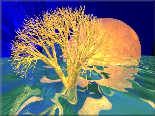
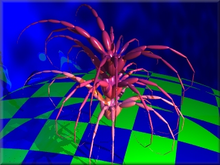
Rekursive Programmierung ist für das Zeichnen von Bäumen und Sträuchern gut geeignet.
Recursive programming is well suited for drawing trees and bushes.
Beispiel E / Example E:
 |
Dieses Beispiel soll einige Bewegungsbefehle demonstrieren:
Z führt eine Vorwärtsbewegung von halber Elementlänge aus, zeichnet jedoch nicht, d.h. der erste Kreis (A=z+FA, gelb) hat "Löcher". Der zweite hellgrüne Kreis (B=-ZB) ist der kleinste, da Z nur halbe Elementlängen zeichnet. Der dritte Kreis (C=^FC, türkis) ist "normal". Beim vierten blauen Kreis, dem größten (D=g&FD) wird durch g eine Vorwärtsbewegung mit voller Länge gemacht, dann erst gezeichnet, er hat also ebenfalls "Löcher".
This example is intended to demonstrate some movement commands: Z performs a forward movement of half the element length, but does not draw, i.e. the first circle (A=z+FA, yellow) has holes. The second light green circle (B=-ZB) is the smallest, as Z only draws half the element length. The third circle (C=^FC, turquoise) is normal. In the fourth blue circle, the largest (D=g&FD), a full-length forward movement is made by g and then drawn, so it also has holes.
15
25
50
E
E=c[A]c[B]c[C]c[D]
A=z+FA           #z: Vorwärtsbewegung mit halber Länge
B=-ZB            #Z: Vorwärtsbew.+Zeichnen der halben Länge
C=^FC
D=g&FD           #g: Vorwärtsbewegung mit voller Länge
@
Beispiel F / Example F:
 |
Hier werden nochmals die Richtungen demonstriert, die man mit ^ + - und & erhält. Sie werden hier mit eckigen Klammern eingesetzt, sodass jeweils zum Ausgangspunkt zurückgekehrt wird. Durch ! wird die Elementdicke verkleinert, durch g(80) entstehen die Lücken.
The directions obtained with ^ + - and & are demonstrated again here. They are used here with square brackets, so that the starting point is returned to in each case. The element thickness is reduced by !, the gaps are created by g(80).
3
25
30
C
C=g(80)c![^FC]+[FC]-[FC]&[FC]
        #Dicke mit 0.7 multiplizieren
        #g(80) Vorwärtsbewegung um 80 Pixel
@
Beispiel G / Example G:
 |
Im diesem Beispiel werden : und ; zur Winkelmultiplikation mit 0,7 bzw. mit 1,1 eingesetzt. Man erhält eine Spirale bei Vergrößerung des Winkels, bzw. eine (Teil-)kreis mit vergrößertem Radius bei Verkleinerung des Winkels.
In this example, : and ; are used for angle multiplication by 0.7 and 1.1 respectively. The result is a spiral when the angle is increased, or a (partial) circle with an increased radius when the angle is reduced.
15
25
20
E
E=c[A]c[B]c[C]c[D]
A=+FA         # F Vorwärtsbewegung + Zeichnen der vollen Länge
B=-ZB         # Z Vorwärtsbewegung + Zeichnen der halben Länge, gibt kleineren Kreis
C=;^FC        # ; Winkelmultiplikation mit 1,1 ergibt Spirale
D=:&FD        # : Winkelmultiplikation mit 0,7 ergibt größeren Kreisradius
@
Beispiel H / Example H:
 |
In dieser Abbildung wurde "(0.5) eingesetzt, d.h. eine Längenmultiplikation mit 0,5. Dazu wurde das Kleinerzeichen für eine Drehung im Uhrzeigersinn um die x-Achse verwendet, die Figur wirkt daher "verdreht".
In this figure, (0.5) was used, i.e. a length multiplication by 0.5. For this purpose, the less-than sign was used for a clockwise rotation around the x-axis, so the figure appears twisted".
4
25
35
C
C=c;!"(0.5)[<^FC]+[<FC]-[<FC]&[<FC]
     # ;Winkelmultiplikation mit 1,1
     # !Multiplikation der Dicke mit 0,7
     # "(0.5)Längenmultiplikation mit 0,5
@
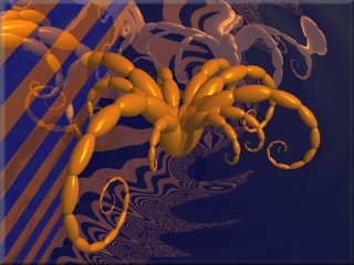
Spiralen mit LParser und PoVRay / Spirals with LParser and PoVRay
Die Theorie zu Spiralen / Theory of spirals
Wählt man sich einen Startpunkt und bewegt sich von dort aus um die Strecke s in beliebiger Richtung, ändert man dann die Bewegungsrichtung um den Winkel a , geht dann um die Strecke s+x in die neue Richtung, dreht man sich wieder um den Winkel a, und so fort, dann erhält man eine BEWEGUNGSFUNKTION:
If you choose a starting point and move from there by the distance s in any direction, then change the direction of movement by the angle a, then move by the distance s+x in the new direction, turn again by the angle a, and so on, then you get a MOVEMENT FUNCTION:
|
Das 2. Teilstück hat dann die Länge s+1x, das dritte die Länge s+2x, ... das n-te Teilstück hat die Länge s+(n-1)x.
Benutzt man Winkel, die ein Teiler von 360° sind (z.B. 120° im obigen Beispiel), dann erhält man regelmäßige Dreiecke, Vierecke, Fünfecke usw.
Oft sehr schön anzuschauende Spiralfiguren erhält man bei geringer Abweichung von den oben genannten Winkeln.
The 2nd segment then has the length s+1x, the third the length s+2x, ... the nth segment has the length s+(n-1)x.
If you use angles that are a divisor of 360° (e.g. 120° in the example above), you get regular triangles, quadrilaterals, pentagons, etc.
Spiral figures that are often very attractive to look at are obtained with a slight deviation from the angles mentioned above.
Für die Programmierung mit PovRay ist LPARSER ideal geeignet.
LPARSER is ideally suited for programming with PovRay.
Bei den ff. Bildern erhält man durch Mausklick das jeweilige Pov-Skript, das zugehörige LParser-Skript ist dabei integriert.
With the following images, you can obtain the respective pov script by clicking with the mouse; the corresponding LParser script is integrated.
In die letzten 5 LParser-Skripte ist mit
noch eine Schwerkraftkorrektur eingefügt, sodass ein räumliches Bild entsteht.t
A gravity correction is inserted into the last 5 LParser scripts with t, so that a spatial image is created.
|
|

|
|

|
|
|
|
|
|

|
|
|
|

|
| © 2025 Asti | PoVRay-Site | Mathematische Streiflichter | Algorithmische Kunst |

|